6 To 1 Pulley System Diagram
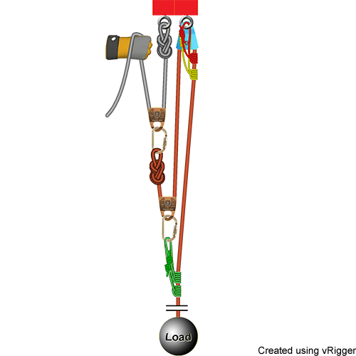
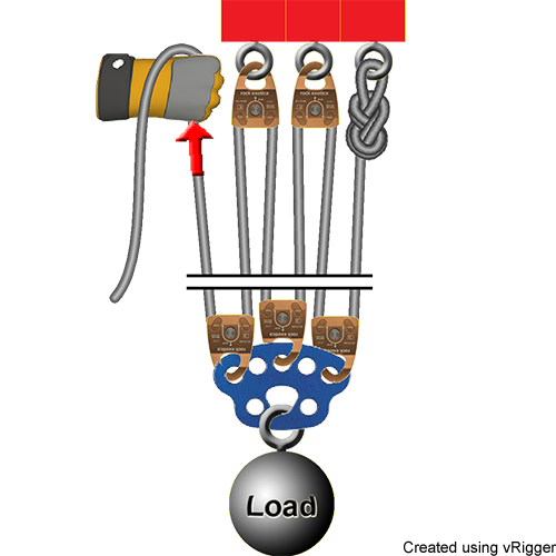
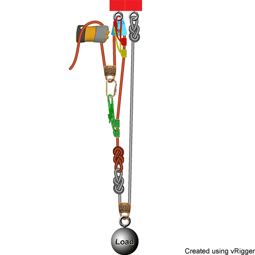
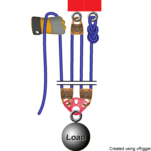
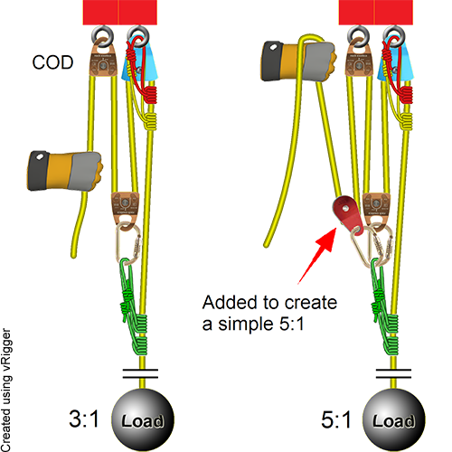
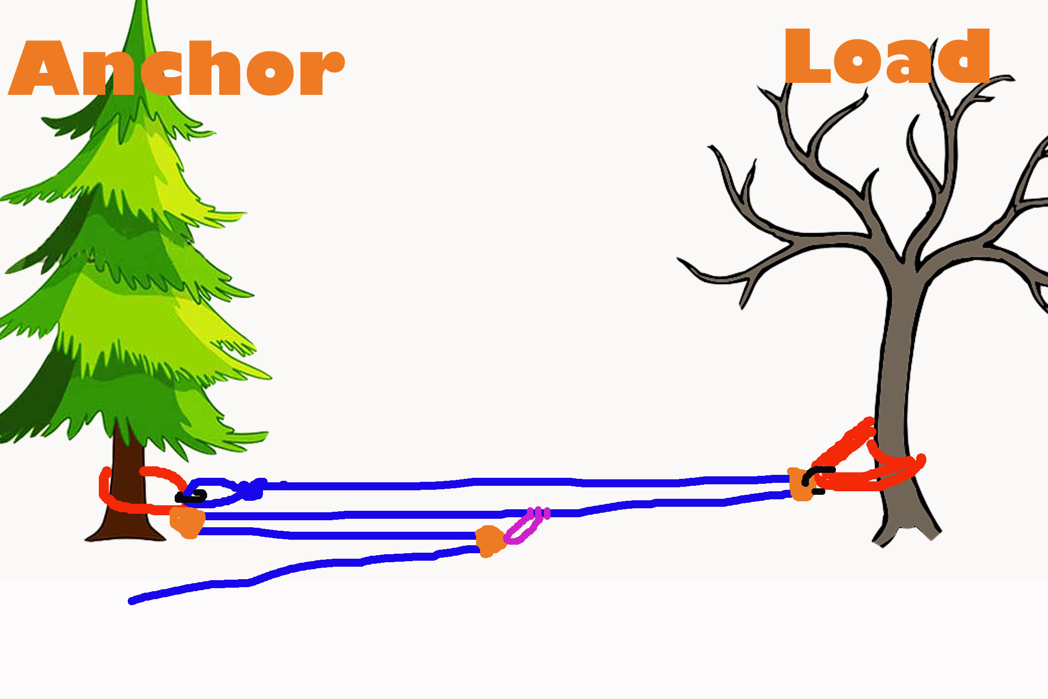
6 to 1 pulley system diagram. If the rope used in the pulley system is tied to the LOAD the ideal mechanical advantage IMA will be ODD ie 11 31. If the tied off end of the rope in a simple pulley system is attached to the load the mechanical advantage will be an odd number. When systems are stacked like this you calculate the combined mechanical advantage by multiplying.
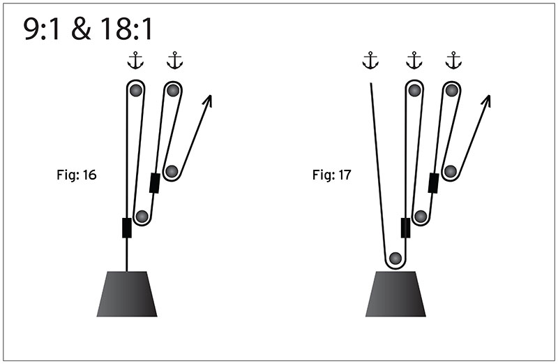
This is easiest to measure if the pulley is placed hub down on a flat surface. In this 61 weve connected a 21 system gray rope onto a 31 system orange rope. They are typically used for hauling and lifting loads but can also be used to apply tension within a system such as in a Tensioned Line or Tyrolean.
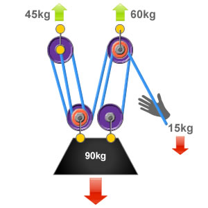
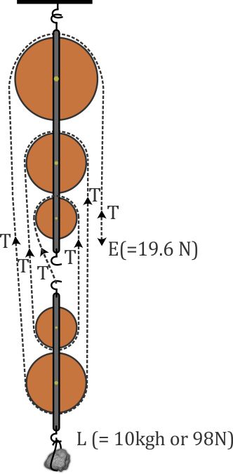
In this system there are three ropes that exert effort on to a load of 90kg so each rope is supporting 13 of the loads weight 30kg. The 41 Pulley System. This pulley system provides a 41 mechanical advantage.
The distance from the edge of the pulleys flange to the edge of the bore adapter or hub. You must decide if you will use a double pulley system with one sheave--the roller in a pulley--in each block which will give. A double pulley has two pulley wheels usually of the same diameter housed inside a single block the two pulley wheels are able.
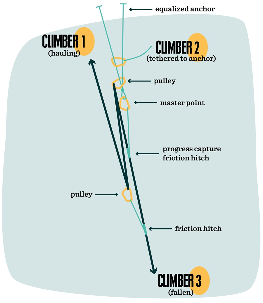
Multiple Pulleys - RPM Reduction. Note that the Reverso acts as a progress capturing device as it allows slac. The mechanical advantage in this system is equal to 1 which means that the force applied on one end of the rope is the same as that being applied on the load to lift it.
Compound pulley systems are created when a simple pulley system is pulling on another simple pulley system. The 21 Pulley System. An easy way to calculate the ratio of a pulley system is to count the amount of lines that apply effort on the load.
Attach the fixed pulley to the overhead anchor point as described in Steps 1 to 3 above. A fixed pulley only changes the direction of the force applied to do work on the load.
They are typically used for hauling and lifting loads but can also be used to apply tension within a system such as in a Tensioned Line or Tyrolean.
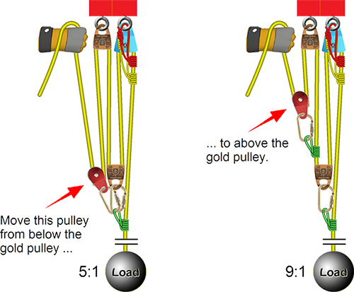
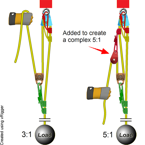
By definition compound systems have one simple system connected to another simple system. Attach the fixed pulley to the overhead anchor point as described in Steps 1 to 3 above. Multiple Pulleys - RPM Reduction. Ropebook 31st July 2019. By definition compound systems have one simple system connected to another simple system. The user is required to apply a force of 25kg to raise this 100kg load for every 4 metres of rope that the user pulls through the pulley system the load will only be raised by 1 metre. It requires less rope than a non-piggybacked 21 system is reasonably easy to rig is easy to add a progress capture device provides an appropriate amount of mechanical advantage to raise one or two people and with a few tweaks it can be converted into a simple 51 system. The 41 Pulley System. 51 etc Even if a change of direction at the anchor does add friction it might make your pull easier depending on your own personal strength body weight and the weight of the load you need to move.
You must decide if you will use a double pulley system with one sheave--the roller in a pulley--in each block which will give. The 21 Pulley System. When systems are stacked like this you calculate the combined mechanical advantage by multiplying. Compound Pulley Systems. It requires less rope than a non-piggybacked 21 system is reasonably easy to rig is easy to add a progress capture device provides an appropriate amount of mechanical advantage to raise one or two people and with a few tweaks it can be converted into a simple 51 system. Ropebook 31st July 2019. If the rope used in the pulley system is tied to the LOAD the ideal mechanical advantage IMA will be ODD ie 11 31.















Post a Comment for "6 To 1 Pulley System Diagram"